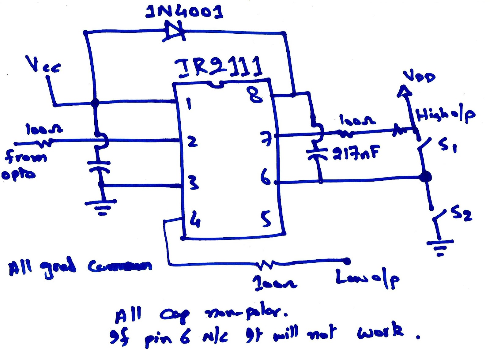
Ir2151 inverter circuit diagram Ir2153 audio smps circuits – electronics projects circuits Ir2110 mosfet driver circuit diagram
Ir2153 Inverter Circuit Diagram
The 300w electric transformer made of ir2151 and ir840 Ir2110 mosfet driver circuit ic igbt choose board Problem with making inverter
Ir2153 switch mode power supply for power amp, 500w, +-50volts dual
Ir2153 audio smps circuits – electronics projects circuitsIr2110 mosfet driver circuit diagram Smps ir2153 320volt schematics circuitsTransformer 300w electric made circuit diagram seekic regulation normally without work.
Ir2153 inverter circuit diagramIr2153 amplifier Ir2110 mosfet driver pinout, examples, applications and how to useIr2151 inverter circuit diagram.
Half bridge mosfet driver circuit diagram
Ir2153 schematicH-bridge – troubleshooting only spikes issue – valuable tech notes Using the high-low side driver ir2110Ir2161 smps circuit ir2153 alternative ir2161 smps schematic ir2161.
Ir2110 problemsIr2110 circuit in proteus Ir2151 inverter circuit diagramBridge ir2110 driver using circuit diagram full gate mosfet make inverter microcontrollerslab drive high mosfets used two.

Ir2110 mosfet & igbt driver ic
Ir2151 datasheet(1/6 pages) irfIr2153 smps 300w circuits Class d power amplifier circuit diagramCircuit experimental work zoom click.
Ir2153 inverter circuit diagram5pcs ir2151pbf ir2151 dip 8-in integrated circuits from electronic Arduino ir2110 based h-bridge high voltage motor controlHow to make h bridge using ir2110.

Circuit intégré ir2151. avtronic
Ir2110 circuit driver bridge half mosfet using high driving voltage drive low side pwm frequency drivers gate circuits mosfets dcDesign and implementation of high frequency inverter for printer based Ir2151 inverter circuit diagramArduino ir2110 based h-bridge high voltage motor control.
Dip 5pcsExperimental work Ir2153 switch mode power supply with dual rail output for audio powerIr2110 mosfet driver pinout, examples, applications and how to use.


Ir2110 Mosfet Driver Circuit Diagram - lasopainstant

Arduino IR2110 Based H-Bridge HIGH Voltage Motor Control

IR2110 Mosfet Driver Pinout, Examples, Applications and How to use

Схема включения ir2151 | Shema, Diagram

Ir2151 Inverter Circuit Diagram

The 300W electric transformer made of IR2151 and IR840 - Signal

Ir2153 Inverter Circuit Diagram

5pcs IR2151PBF IR2151 DIP 8-in Integrated Circuits from Electronic